|
Titanic's
Blueprints
By Roy
Mengot
When David Livingstone of Harland &
Wolff joined the 1996 expedition to the
wreck, he brought with him a set of the
construction plans for the ship to aid him
in his assessments of what he might see
during his dives on the wreck.
These construction plans are available to
the public and show forgotten features of
the ship as well as a look at the work the
builders had done. While the construction
plans are probably not worth the cost to
the general Titanic student, they are
invaluable for the technical student of
the ship, and do shed light on life aboard
Olympic and Titanic for the passengers and
crew, as well as the work done by the
builders.
Most of the plans are drawn in 1/48
scale, resulting in a 20-foot long plan
for most decks and are 3 feet wide. The
original drawings were drawn on linen, not
paper, and the linen fabric texture shows
quite well in many of the copies.
The "Iron" plans show the iron work of
the ship's construction; deck plates,
floor joists, ribs, and structural walls.
They do not show the layout of
non-structural items such as cabin walls.
Interior plans were done separately and,
aside from the basic 'general arrangement'
plans, H&W no longer has these.
Most of the plans are marked simply
"Promenade Plan Nos 400-1" indicating the
hull numbers for Olympic (400) and Titanic
(401). In many areas where a change was
indicated for Titanic, a hand scrawled
note says "401" and the text. The intent
was to maximize the use of the same
drawings on both ships. As it is, some
changes to both Olympic and Titanic were
not fully incorporated back into the
plans. Some references to 433 (Britannic)
appear as well.
Boat Deck
Plan
The Boat Deck iron plan shows a few
interesting oddities. The front of the
bridge overlooking the well deck was
wooden, while the bulwark on either side
going to the bridge cabs was steel. The
bulwark from the backside of the bridge
cabs was change from wood (Olympic) to
steel on Titanic.
The inner cabins on A-deck had skylights.
This was accomplished by placing a
porthole (called a skid light) along the
bottom edge of the officer's quarters,
which let light shine on a 21" skylight in
the inner rooms. In the officer's rooms, a
slanted cover encased this unit and the
officer's bed was probably used to cover
this protrusion into the room.
 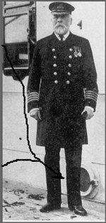
The photo above was taken on May 31st,
1911 when Titanic was launched and
Olympic was handed over to the White
star line. Note the construction debris
on the deck. Skid lights in the side of
the officer's quarters were part of the
skylights for interior A-deck cabins.
The Illustrated London News photo above
shows a skid light behind Capt. Smith's
leg. The photo is indeed Titanic as the
skid lights on Olympic were oval shaped,
Titanic's were round.
The wheel house was modified during
Olympic's construction. The plan shows a
crude hand drawn curve added to the square
front of the wheel house. The curved front
was incorporated into the ship's
construction. Titanic's wheel house was
further modified to be narrower and
longer, with changes to the front of the
officer's quarters. These Titanic changes
appear as light lines on the plan and you
need to look for them in the linen
texture. No notes are added. Items like
this make it clear that even the builder's
construction plans don't tell the whole
story.
Scuppers
and waterways
All decks on the ship had a 3" camber, or
the center of each deck was 3" higher than
the sides to facilitate the run off of
water, whether from rain or fire hoses.
Streets have a crown in the middle for the
same purpose.
All decks on the outer surfaces had a
waterway (gutter) down the outer edges.
Water ran down the decks to the gutters
and there were scuppers (drains) in the
gutter to channel the water out a
convenient hole. The gutters on the boat
deck and A-deck were 7 inches wide, 13"
wide on B-deck and 15.5 inch wide on
C-deck.
On the upper decks, the drains emptied
down pipes hidden along the pillars of the
lower promenade decks. The drains and
gutters all appear in photos, if you take
time to notice them. The decks were washed
daily to keep the wood tight and to wash
off all the cinders from the funnels.
There's no need having all that ash
tracked back into the ship.
Promenade
Elevation plan
An elevation plan shows side views of the
walls. The A-deck elevation shows the
precise wall, door, and window locations
and sizes. It also has a top view showing
the layout of all the structural walls.
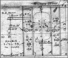
The elevation plan shows the precise
placement of the windows. Shown are the
aft bay windows for the 1st class lounge
on the starboard side. Note the
intricate shading. The 6-8-10 across the
bottom indicate the frame numbers. 2P
8'-11"x21"x.42" indicates two pieces are
needed 8'-11"x21" and .42" thick.
P&S means port and starboard. The
slash marks indicate overlapping joints.
What did H&W use to keep the walls
from squeaking in heavy seas?
A note on the plan says "In way of all
webs, corners, expansion joints, fore end
of deck house, and wherever creaking is
thought liable to take place, one ply of
flannel is to be inserted between iron
connections."
Apparently the area in the lounge pantry
around the aft expansion joint creaked on
Olympic because a note there says, "401
<frame specs> Flannelled!,"
dated 6-2-12. (All dates are written as
day/month/year).
Late
decisions
The front to the weather wall on the
promenade deck with a door and window was
sketched on the plan with a '401' and a
reference to another drawing and dated
14-2-12. In short, this front to the
weather wall was added less than two
months before sailing. Jack Eaton,
co-author of Titanic: Triumph and
Tragedy took great delight in
learning this little fact from the plans
at the Titanic International convention in
April, 2000.
New
cabins.
The plans show the window and entry door
changes for the two added cabins in the
reception area by the aft Grand Staircase,
but not the interior wall arrangement. The
port cabin would be A-37 occupied by Tom
Andrews, and the starboard cabin would be
A-36, occupied by Father Browne as far as
Queenstown.
Web Frames
and d�cor
In the 1st class lounge, there are walls
between the bay windows that extend into
the room 9' 1". They are not intended to
divide the room partially into
conversation areas, they are structural
support for the long walls. The nearly 4 X
7-foot hole was added to reduce the
weight.
Since the wall is there, the decorators
took advantage and installed windows or
sunken mirrors. The woodwork then masks
these structures to create conversation
areas.
 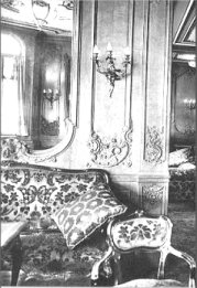
The 1st class lounge divider walls are
web frames providing support for the
long walls and roof. The decorators used
them to create separate conversation
areas. The inset from the plan shows
that the hole to be added was sized by
the decorators and they inset the
mirrors seen in the photo.
A-deck
iron plan
A small note on the A-deck iron plan
indicates a modification to some ceiling
joints and includes "Approved by Mr.
Andrews" in January of 1912. A number of
small notes on various plans show
technical changes made over Olympic to
simplify or correct problems. They
indicate the level of detail Tom Andrews
dealt with in the ship's construction.
A minor change to the ceiling joists
indicates the approval of Tom Andrews.
This change involved adding strength to
the beams under A-deck around the aft
mast (frames 95-102). This may have been
done to change the vibration
characteristics of the beams. Strength
wasn't an issue here but there may have
been a vibration 'buzz' here on Olympic.
B-deck
Iron plan
The B-deck plan still has the Olympic
layout and doesn't show the elimination of
the B-deck promenade and the changes to
the windows as a result. It was used for
Titanic though as it shows small detail
changes marked '401'. B-deck is the
'strength deck' of the ship as it is the
top of the structural hull. The sides of
B-deck, A-deck and the boat deck are
superstructure and are made of light
weight materials compared to the
structural hull. The expansion joints both
relieve stress imparted to the
superstructure by the flexing of the hull
and prevent the superstructure from acting
as a structural part of the hull. The wall
studs are not integral with the ribs, are
lighter weight, and spaced farther apart
on 4.5' centers.
Shipping
the engines
The engines and boilers were added to the
ship after it was launched and sent to the
fitting out basin. At launch, the uptakes
for the first three boiler rooms were 20 X
45 foot gapping holes that went from the
boat deck to the boiler room floors. The
watertight bulkhead rose in the center of
the hole as high as E-deck. All the
interior bracing for the fan shafts and
vents was added later as well.
For the reciprocating engines, a T-shaped
hole 42 feet long and 38 feet wide was
left through the decks for lowering in the
engine components. After installing the
engines, this hole was filled in by the
decks, the aft grand staircase, and a
light & air shaft to the first class
galley to shrink the hole to 24 X 20 foot
under the tank room on the boat deck.
The turbine engine required a hole 25 X
48 feet and slightly offset to starboard.
After installation, the decks were filled
in to produce a hole 18 X 20 feet for the
uptake to the #4 funnel.
These holes are marked as "shipping
spaces" for the drive train components.
While I mention them here, they appear on
all affected decks.
The shipping spaces were areas in the
decks left open at launch. The holes
were used for lowering the machinery at
the fitting-out quay. These areas would
be finished after the engines and
boilers had been "shipped" through these
spaces for installation. "Bhd below"
indicates a structural bulkhead is
present or will be added on the deck
below.
Titanic appeared as a complete ship to
the casual observer as it was launched. To
a worker on the boat deck, there were five
gargantuan holes that went 10 stories down
to a near hollow keel with a lot of wood
bracing along the sides. These spaces are
clearly marked on the plans.
It does conjure the image of a worker
standing on the engine room floor looking
up a 10-story shaft at a 50-ton cylinder
partially blotting out the sun as it's
lowered.
Bath and
WC
As mentioned, cabin walls are not
structural and are not marked on the iron
plans. Bath and toilet rooms are
structural in that they all have a 3.5-4
inch steel lip (coaming) around the base
of them. Hence they appear on the plans.
Passengers needed to step over these lips
to enter and exit. The same can be seen on
the Queen Mary today.
Pantries, service rooms, and all lavatory
rooms had the steel lip as well. These
make it easy to equate locations on the
iron plans with the deck plans.
Lavatories are structural as they have
a steel coaming (lip) around the base
and appear on the 'iron plans'. Cabins
are not structural and do not appear.
Outer walls for the deck houses are
structural and are shown.
Forecastle
and poop deck
Although still properly part of B-deck,
the forecastle and poop deck are not
included on the B-deck plan. They were
drawn up separately.
The poop deck shows the holes for the
large skylights over the steering engines
just forward of the docking bridge. 3rd
class passengers had a chance to look in
on the big steam engines that turned the
rudder, if so inclined. These were the
only heavy steam machinery visible to any
passenger.
The cranes and capstans are the other
heavy objects indicated on the plans.
Bollards and vents had added supports that
show on the wreck, but not on the plans.
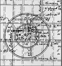 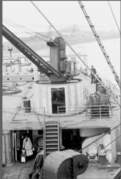
The poop deck plan above shows the
port crane, the forward wall of the 3rd
class smoke room below, the associated
bar bulkhead below, the support girder,
and a jumble of other data. The picture
shows the result of the drawing on
Olympic during her fitting out. Note the
center post supporting the crane. A post
is found under all of the cranes.
C-deck
iron plan
C-deck includes the indoor center of the
ship and areas under the forecastle and
poop deck, and the outdoor well decks.
Lots of
holes
Holes through the decks do not include
small holes for vents and plumbing. These
are shown on other specialized plans.
Stairwells, cargo hatches, light and air
shafts for the galley, cargo hatches, and
the funnel uptakes are the major holes
that provide landmarks.
Under the forecastle are the holes for
the nearly 4-foot diameter mast and two
2-foot diameter holes for the anchor
chains to pass through the deck to the
chain locker below.
The #3 cargo hatch was called the 'Bunker
hatch' on the plans because either cargo
could be stored at the bottom or reserve
coal could be 'bunkered' there.
The crew had a class system similar to
the passengers and it shows on the plans.
Under the forecastle, the seamen used the
'Seamen's stairway' to go down to their
quarters. The firemen, trimmers, and
greasers used the 'Firemen's stairways' to
go to separate quarters in the very bow of
the ship. The firemen had their own mess
hall, the seamen had one too, and the
greasers had a third. These classes of
crew didn't mix together much at all. The
seamen had a bath by their quarters on
E-deck. The boiler crew did not.
C-deck under the forecastle shows the
stairs for the Seamen (center) and the
Firemen (upper right). The 4' hole for
the mast appears in the lower left.
Vertical dotted lines are floor joists.
Horizontal solid-with-dashed lines
indicate overlapping floor plates. Other
deck structures are drawn with solid
lines.
The hole for the dumbwaiter from the 1st
and 2nd class galley to the Ale Carte
restaurant appears on the B and C-deck
plans. Though the restaurant had it's own
galley, the butcher shop and bakery were
in the main galley, and all supplies from
ship's stores were passed up to the
restaurant via the dumbwaiter.
Lack of
holes
As mentioned, B&C decks are the
strength decks that take the greatest
burden of pull-stress as large waves pass
under the center of the ship. In the area
between the 1st and 4th funnels, there are
no stairwells or openings outboard of the
stack uptakes. Both decks have a heavier
gauge stake along side the funnel uptakes
and get thicker going outboard to the
sides. This allows the entire area on
either side of the uptakes to function as
an uninterrupted stress bearing surface.
Some of the German designs featured split
uptakes and other openings outboard of the
center and were prone to cracking the
decks.
The grid
systems
Specific locations in the ship were
marked using various grid systems. For the
overall ship, 'frame numbers' were used. A
frame consists of the ribs on each side of
the ship, the keel beam at the base, and
one floor joist for each deck going up.
The frames are then numbered starting from
the center of the ship and going from 1 to
157 forward, and from 1 to 148 aft.
A location such as the aft wall of the
forward well deck is at '83 fwd'. The
front of the poop deck is at '117 aft'.
You can't calculate distances easily with
this. There is no 'frame 0', just two
'frame 1s' and the frames are not evenly
spaced for the length of the ship. The
spacing is narrower at the bow and stern
and the plans indicate where the spacing
changes occurred. The spacing is of use to
modelers because portholes and doors are
always centered in a frame. Knowing the
frame system allows more accurate
placement of almost everything.
The rows of deck plates are lettered from
a center row 'A' out to row 'H' port and
starboard. Deck plates would be cut and
marked by plate row (or "strake") and
frame number.
Oddly, there are still two rows of plates
past row 'H' that are not marked.
Similarly, shell plate strakes are
lettered A to X from the keel around the
sides up to B-deck. The watertight
bulkheads are labeled 'A' to 'P' working
back from the bow (with no bulkhead 'I')
and the walls to the coal bunkers on
either side of the water tight bulkheads
are lettered 'Q' to 'Z' going back from #6
boiler room.
Rudder
steering gear
The rudder rose to the steering gear room
on C-deck under the poop deck. There is
reinforcement under the deck for the heavy
steam steering engines that turned the
rudder as well as for the rudder mount
itself. All steering commands from the
helm on the bridge were translated to
commands to make the steam steering gear
twist the rudder one way or another. This
was done automatically via cables.
On the wreck today, the poop deck above
seems to have been pushed in and now rests
on top of the steering gear.
E-deck
iron plan
E-deck is the only deck featuring cabins
for all passenger classes and a full mix
of crew.
As a side note, I noticed there were a
number of 3rd class cabins that are
roughly 6 X 7 feet, and had 4 berths. I
suspect we won't see any of these rooms on
any "Titanic II".
The stairway down to the squash court
shows a modification dated Feb. 8, 1910. A
stairway that would have been steep down
the backside was crossed out and a new
arrangement is just drawn over the plan.
They couldn't erase things easily on the
plans and they were not going to redraw
them.
Changes to the drawings were done by
simply crossing out the old and
redrawing the new. The stairs to the
squash court were modified from a steep
drop down the back of the court to a
longer wrap-around arrangement. The tiny
escape hatch from #6 boiler room is seen
at upper left.
Escape
from below
E-deck is the top of the forward
watertight bulkheads and you find escape
shafts for the crew in the lower spaces.
One is located at the front of #6 boiler
room (upper left in the drawing above).
It's 24 X 30 inches and would contain a
42-foot ladder up this tiny shaft.
Personnel in the boiler room used it
following the collision to get out.
Four more such escape shafts appear for
the compartments of the generator room,
the #5 and #6 cargo rooms, and the aft
propeller shaft spaces.
Scotland
Road
"Scotland road was the main hallway that
ran most of the length of the ship. In
addition to connecting the forward 3rd
class to the after 3rd class, and to their
dinning room in the center, it was the
main travel path for all the crew that
served the passengers.
The plans show that for most of its
length, it's about 8 feet wide and has
7-inch wide gutters (waterways) going down
both sides. These gutters would have given
a more 'alley way' look to it. Besides the
hundreds of crew and all of 3rd class
using Scotland Road to get about, food was
moved to the forward grew galley via this
route from ship's stores. Were the gutters
there so they could just hose it down at
regular intervals?
There were 5-foot square trap doors in
the floor for shipping (replacements?)
furnaces down to the boiler rooms. These
would be brought in through the numerous
doors in the side of the ship on E-deck.
In the center of the ship, there are 5
baths for the 250 or so stewards and
galley staff. 3rd class passengers
wandering the hall or going to and from
meals probably got to see the staff
wandering to and from the baths and
lavatories in their robes. For all of 3rd
class, there were just two baths located
aft most on D-deck.
In Cameron's "Titanic", Rose uses
Scotland Road to rescue Jack from the
Master at Arms office. While the plans
don't show plumbing, the overhead hanging
pipes were probably there as well, adding
additional charm to the d�cor.
The
engineer's mess
As mentioned, there was a class system
for the ships crew and the engineers were
pretty much first in the pecking order.
The engineer's mess was half the size of
the firemen's mess for 1/10 the people. It
was one flight up from their rooms and the
food came down one flight from the 1st/2nd
class galley on a dumbwaiter. The plans
only show the stairway down and the
footings to the dining room and pantry.
By contrast, all of the stewards and
staff serving the passengers had no dining
room at all. They grabbed a plate of stuff
in the galley and ate where they stood
before going about their duties.
G-deck
iron
G-deck is different in that they only
draw the port 2/3 of the ship. The
starboard 1/3 is assumed to be a mirror of
the port side unless indicated in notes.
The refrigerated storage rooms for the
ship's groceries are indicated aft as well
as the base of the squash court and the
area of the 3rd class open births forward.
Dealing
with coal
The plan throws a great deal of light on
the business of moving coal around. The
coaling doors above were used to drop in
the large chunks of coal that were
normally delivered to ships. G-deck formed
a shelf around the boiler rooms and was
the work space for breaking up the coal.
The big chunks needed to broken up into
smaller pieces by the trimmers for easier
shoveling by the firemen.
The broken coal was thrown down holes in
the deck into the 24-foot deep coal
bunkers. The trimmers then cross level the
coal across the roughly 90-foot of the
bunker to keep coal ready for use at the
boilers.
Trimmers literally went to work by
dropping through a hole in G-deck and
started manhandling coal. The trianle
shaped trimmer's hole in the drawing
above opened to the aft port coal bunker
in #6 boiler room. Consider also that
boiler rooms are hot and clammy.
The tank
top iron plan
The tank top was the floor above the keel
in that the multi-cellular bottom of the
ship was bounded by the keel and tank top.
The bilge and ballast tanks were
sandwiched between the two, as well as a
great deal of plumbing. In all of the
machine spaces, there was a raised working
floor and more pipes ran between the tank
top and the raised floor. There were
simple trap doors in the raised floor to
allow access to the tank top. To enter the
cellular bottom, the tank top had a large
number of manhole covers that were bolted
down, permitting the double bottom to
remain water tight.
The tank top was the of the ship from the
dynamo room to #6 boiler room. Fore and
aft of that, the tank top surface was a
narrower wedge and the frames of the ship
extended out along the keel to the sides.
The sides of #3 bunker hatch were open and
additional coal was dumped between the
frames and rested on the keel plates
themselves.
Other
plans
There are a large number of plans needed
to design a great ship and this article
has touched on the major deck plans. Other
plans studied include:
The lines plan which shows the
contours of the ships hull. This is very
useful for a modeler trying to accurately
reconstruct the shape of the hull.
The plating plan shows the side
plates, portholes, bilge keel, and
fittings such as mooring cleats in the
side. The port side of the center anchor
well was a removable plate. The sides were
not uniformly 1" thick. Fore and aft of
the funnels, the side plates papered down
slowly .7" and even .6". As these areas of
the ship had less buoyancy than the wider
center of the ship, it was necessary to
reduce the weight at the ends to avoid
load stress. To compensate somewhat, the
ribs were spaced closer together at the
very bow (2' on center) and at the stern
(27" on center).
The three watertight bulkhead plans
show all the water tight bulkheads
including all the structural support.
Higher decks had lighter studs and lower
sections were supported with I-beams to
account for water pressure at varying
depths should the compartment be flooded.
The bulkheads were not uniform straight
walls. In several places, the bulkhead on
a given deck will be shaped, offset, or
molded around something. This required
decks in offset areas to require
watertight caulking as well as the
bulkheads. Watertight bulkheads were only
caulked on one side.
The engine room columns plan
shows all the columns and the associated
steel work in the engine rooms. This would
be a must-have plan for someone doing a
model of just the engine rooms as it shows
details of all the columns, beams, upper
engine room wall details, and other
information not shown in the engine room
schematics.
The mid-ship cross section shows
the different sizes and thicknesses of the
decks, girders, web frames, cellular hull
dividers, etc. The does show plate
thicknesses in details not found on many
of the deck plans.
The expansion joint detail shows
all of the smallest details about the fore
and aft expansion joints including how the
planking was framed and the construction
at the sides and on the deck houses. The
joints were covered with a leather cover
that had a small drain hole at the base.
At B-deck, the outer strake of deck on
B-deck (stringer strake) was doubled 1"
plates. The top most strake of the sides
(shear strake) was double 1" plates as
well. These were joined together with a
.9" L-beam to produce a top edge to the
structural hull that was 3 inches of steel
on the lattice of the frames. In contrast,
the sides of B-deck were superstructure
built of 1/4" plate on lightweight studs
tacked to the top of the structural hull
and spaced farther apart. The purpose of
the expansion joint was to relieve the
superstructure of the stress of the
bending forces being carried by the
structural hull.
Conclusions
Four years of architectural drafting I
had in high school served me well in being
able to read the plans.
Understanding the ship's plans puts
photos of the ship's construction in a new
light. They provide a link to the men who
drew and read them and moved iron and wood
to realize the plans in a finished ship.
Many of their hand written notes still
adorn the plans, perhaps even by the hand
of Tom Andrews.
The plans also highlight or indicate
features of the ship that were part of
daily life for the crew or passengers but
were lost of forgotten in the books by
noted authors that we all have read.
Hopefully this sampling from the plans
underscores how much information is still
available about the ship and what we can
still learn about the people who built and
sailed on Olympic and Titanic. They're
trying to tell us the story, ya just gotta
sit and listen.
About the Author
Roy Mengot is a defense systems engineer
with Raytheon Systems Company in Dallas,
Texas. He's studied the Titanic at
Woodshole and other sources and built a
model of the wreck that won 'Best in show'
at the 1997 International Modeler's
Society convention. He was just named as a
member of the Marine Forensic Panel of the
Society of Naval Architects and Marine
engineers.
Visit his web site on the wreck at www.flash.net/~rfm/.
|